DESCRIPTION
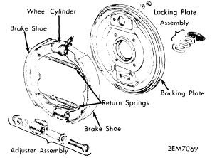
Brake system is hydraulically operated, using a tandem master cylinder and a Master-Vac power brake unit. Leading-trailing shoe/drum brakes are used on all four wheels, with front brakes actuated by uni-servo wheel cylinder, and rear brakes actuated by a duo-servo wheel cylinder. Parking brake is cable actuated, operating secondary shoes of rear brake assemblies.
ADJUSTMENT
BRAKE PEDAL
Loosen stop light switch adjusting nuts and rotate switch until pedal, height, measured from pedal to floor, is approximately 5.5". With pedal height adjusted, adjust brake pedal push rod adjusting nut so that .039 - .118" free play is obtained, when depressing pedal. With pedal assembly properly adjusted, total pedal travel should be 4.96 - 5.20" with no interference.
BRAKE SHOES
Remove rubber boot from hole in front backing plate and lightly tap adjuster housing to move it forward. Using a suitable brake adjusting tool, turn adjuster downward until drum locks, then back off until drum is free to rotate. Adjustment procedure for rear brakes is the same, with parking brake fully released.
PARKING BRAKE
With parking brake lever applied 3.15 - 3.94", adjust equalizer link with adjusting nut until rear wheels are locked. Release parking brake and insure rear wheels turn freely.
HYDRAULIC SYSTEM BLEEDING
Attach a bleed tube to wheel cylinder bleeder screw, and immerse opposite end into a container partially filled with brake fluid. Pump brake pedal two or three times, open bleeder screw to allow air to escape, then close bleeder screw. Continue operation until air is no longer seen in discharged fluid. Repeat procedure on remaining brake lines. Bleed rear wheel first, front wheel last.
REMOVAL & INSTALLATION
BRAKE SHOES
Installation - Reverse removal procedure. NOTE - Apply a thin coat of suitable brake grease to pivot points on backing plate adjuster and spring sliding surfaces.
Removal (Rear) - Remove rear wheel and brake drum. Remove mounting springs, clips and pins. Spread shoe assembly and remove parking brake strut. Disconnect return springs and parking brake cable, then lift off brake shoes. Remove adjuster assembly from backing plate.
Installation - Reverse removal procedure. See NOTE preceding installation procedure.
WHEEL CYLINDER
Removal (All) - With brake shoes removed, disconnect hydraulic line from cylinder and nuts attaching cylinder to backing plate. Remove wheel cylinder
Installation - Reverse removal procedure, adjust brake shoes, and bleed hydraulic system.
MASTER CYLINDER
Removal - Disconnect hydraulic lines from master cylinder taking care not to spill brake fluid on point. Remove nuts attaching master cylinder to power unit and remove cylinder.
Installation - Reverse removal procedure and bleed hydraulic system.
POWER BRAKE UNIT
Removal - With master cylinder removed, disconnect vacuum line from power unit. From inside vehicle disconnect brake pedal return spring, power unit push rod clevis from brake pedal, and remove nuts attaching power unit to firewall. Remove power unit from engine compartment.
Installation - Reverse removal procedure, adjust brake pedal assembly, and bleed hydraulic ssytem.
Push Rod Adjustment - Adjust master cylinder push rod height to .394 - .413", measured from tip of push rod to master cylinder mounting surface of power unit.
Check Valve Replacement - Vacuum check valve is located in vacuum line between intake manifold and power unit. To remove, loosen hose clamps, separate hoses from valve and remove check valve. To install, reverse removal procedure.
OVERHAUL
WHEEL CYLINDER
Disassembly (All) - Remove snap ring and rubber dust boots. Remove piston and seal assemblies, then remove seals from pistons.
Cleaning & Inspection - Clean all parts in clean alcohol or brake fluid.NOTE - DO NOT use mineral based solvents. Inspect all parts for wear or damage; replace parts as necessary. Check clearance between piston and cylinder bore; if clearance exceeds .006", replace cylinder or piston as necessary.
Reassembly - Reverse disassembly procedure and note the following: Coat all parts with clean brake fluid when reassembling. When securing connector bolt, insert location tip to hole of wheel cylinder firmly and tighten securely.
MASTER CYLINDER
Disassembly - Remove reservoir caps and drain fluid. Remove retaining ring and secondary piston stop bolt, then withdraw stop washer, primary piston assembly, secondary piston assembly, and return springs. Remove valve caps and check valve assemblies.NOTE - DO NOT remove reservoir. If removed, a new replacement reservoir must be installed.

Cleaning & Inspection - Clean all parts in alcohol or brake fluid. Inspect all parts for wear, deformation or other damage, replace parts as necessary. Check clearance between pistons and cylinder bore; if greater than .006", replace parts as necessary. NOTE - Manufacturer recommends replacing cups and valves whenever master cylinder has been disassembled.
Reassembly - Reverse disassembly procedure and note the following: Coat all parts with brake fluid or rubber grease when reassembling to prevent damage. Replace all gaskets and packing with new parts.


1 comments:
With these steps it is fun repairing hydraulic brake system well
the maintenance cost of the hydraulic brakes are almost none but greasing must be done time to time and most important check for any leak as it may malfunction them.
Thanks
Henry Jordan
Hydraulic Seal Kits
.
Post a Comment